LumiNode Advanced Networking
In this article we will look at how to configure the network and advanced network options of the LumiNode. Firmware 2.3.0 or higher is required for these features. The interface has been redesigned in firmware 2.5.0.

Note: It is not recommended to connect both network ports of the LumiNode to the same network. If you need a connection on multiple groups to the LumiNode, it is recommended to configure one of the network ports as a trunk port and connect this to a trunk or ISL port on your switch.
v2.5.0 and newer
This section has been updated based on firmware version v2.6.1 and should apply to v2.5.0 and newer.
Enable advanced networking mode
- Go the "Network" tab in the LumiNode web interface (1) and select 'Advanced' networking mode (2):
- This 'Advanced' networking page is divided in 3 sections:
- Action bar (3):
- Assign group - Used to assign a group or trunk to a physical network port or virtual networking interfaces.
- Edit groups - Used to edit the group configuration. By default the configuration will contain the 20 predefined groups that you might know from GigaCore. Custom groups can be added.
- Edit trunks - Used to edit the trunk configuration. By default this contains 'ISL' (Inter-Switch Link), a trunk containing all 20 predefined groups. Custom trunks can be added.
- Add interface - Used to create a new virtual networking interface.
- Physical port configuration (4). This shows which groups or trunks are assigned to the physical networking ports on the device and how the groups on these ports are connected between these ports.
- Virtual networking interfaces (5). This gives an overview of the 'virtual' groups used by the LumiNode. This contains the IP configuration for this interfaces and the permissions for this interface
Add a new virtual interface
- To add a new virtual interface, select "Add interface" (6) and choose the group you would like to use (7). A group can only be used for 1 virtual interface, so groups that are already used will be disabled.
Each virtual interface needs at least 1 valid IP address and prefix length (8). The IP address and subnet are shown in CIDR notation. The IP address is shown first, followed by the prefix length after the '/'. The prefix length represents the bit-length of the IP prefix or subnet mask. The most common values for the prefix length and the corresponding subnet mask are:- 8: 255.0.0.0
- 16: 255.255.0.0
- 24: 255.255.255.0
- Additional IP addresses can be added using the '+' button (9). The order of the IP addresses will not be stored inside the device and is not relevant.
- When multiple IP addresses are configured for a virtual interface, an IP address can be removed using the bin icon (10) next to the IP address.
- When multiple virtual interfaces are configured, a virtual interface can be removed by using the bin icon in the top right of the interface (11).
- The permissions of the virtual interface can be selected:
- Use the virtual interface for input/output of networked lighting data (12). Only 1 virtual interface can have this enabled on a LumiNode. Use a LumiCore if you need multiple input interfaces.
- When 'Output' is enabled on an interface and multiple IP addresses are configured, select the IP address that should be used for outgoing networking packets with the 'output' icon next to the IP address (13)
- Use the virtual interface for configuration (14). When disabled, it will not be possible to access the web interface through this virtual interface.
- All virtual interfaces can be used for SNMP monitoring and 'ping' testing.
- The '1' and '2' in the top bar of the virtual interface (15) indicate on which network port the group of this virtual interface is configured. A greyed out number indicates that the group is not present on that particular port, a white background indicates that the virtual interface can be accessed through that physical network port.
- The color and text in the top bar represent the name and color of the group assigned to this interface (16).
- Use the "save" button in the top right of your screen to save your configuration when you are happy with your changes.

Warning! This is advanced network configuration. Changing the group configuration and 'allow config' options for a virtual interface can result in the LumiNode becoming unreachable. Verify that you will still be able to access the device before saving the configuration.
Edit group configuration
To change the name or VLAN ID of a group:
- Select "Edit groups" (1) in the action bar.
- Select the group you would like to edit (2)
- Change the VLAN ID and/or name. For custom groups, the color can be modified as well.
- Save your configuration (3)
Warning! This is advanced network configuration. Changing the group configuration and 'allow config' options for a virtual interface can result in the LumiNode becoming unreachable. Verify that you will still be able to access the device before saving the configuration
Assign a group or trunk to a physical port
To assign a group or trunk to a physical port:
- Select "Assign group" from the action bar (1)
- Select the group or trunk you would like to assign (2)
- Click on the port(s) on which you would like to assign the group or trunk (3)
- Save your configuration (4)
Warning! This is advanced network configuration. Changing the group and trunk assignment can result in the LumiNode becoming unreachable when not configured correctly.
Assign a group to a virtual interface
To assign a group to a virtual interface:
- Select "Assign group" from the action bar (1)
- Select the group you would like to assign (2)
- Click on the colored portion of the virtual interface(s) on which you would like to assign the group (3). A group can only be used for 1 interface.
- Save your configuration (4)
Warning! This is advanced network configuration. Changing the group assignment can result in the LumiNode becoming unreachable when not configured correctly.
Process engine indication
When advanced networking is enabled, the networked inputs and outputs will show the group used for Input/Output data. A LumiNode can only use 1 group for input and output. If you would like to use multiple groups for input or if you would like to use a different group of input and output data, use a LumiCore.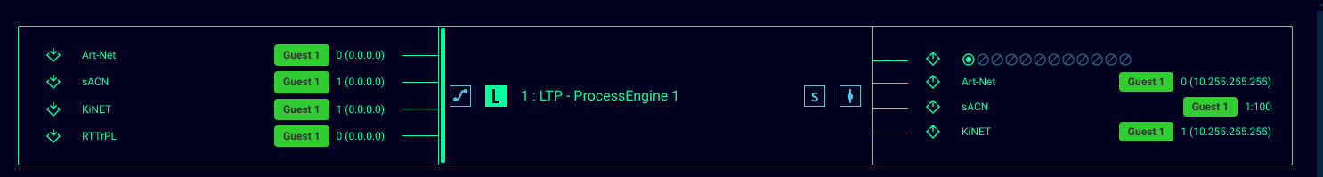
Practical examples
Art-Net inputs from different IP ranges
Art-Net data is broadcasted, so it is important that source and receiver are part of the same IP subnet. Console operators are not always in the ability to modify their IP configuration to match the IP subnet of a venue. This can easily be solved by adding another IP address to the LumiNode. If you use networked outputs, make sure to select the IP address you would like to use for outgoing network packets.
In this example, the 'house' network is using the default 2.x.x.x/8 IP range, but a guest comes in with a console that is for some reason configured for 192.168.1.x/24.
In this example, the 'house' network is using the default 2.x.x.x/8 IP range, but a guest comes in with a console that is for some reason configured for 192.168.1.x/24.
- Add another IP address to the virtual interface (1)
- Select the IP address you would like to use for outgoing network packets (2)
- Save the configuration.
Pass through a group to a second network port
It is possible to forward a group or trunk between the 2 physical network ports of a LumiNode. This can be useful in various situations where switch ports are limited or where you would like to avoid additional network cabling. This can be an intercom system, the camera feed for a RoboSpot system, the management group of your switches,...
- Select "Assign group"
- Assign a trunk (ISL) to the network port that will be used to connect to your switch. Make sure to use the same trunk configuration on your switch. Also make sure that the trunk contains the group used to configure the LumiNode so you can still access and use your LumiNode
- Assign the group you would like to forward to the other network port.
- Save your configuration
Split configuration and lighting data
It is possible to separate configuration of the LumiNode and the actual lighting data in separate groups.
- Assign a trunk to the physical network port(s) that contains both the management and data group
- Add a new virtual interface for the data group
- Disable 'input/output' on the management interface and enable 'input/output' on the data interface
- Give the data interface an IP address. Since this will not have 'allow config' enabled, the IP address can be in the same IP subnet as management, but it is recommended to use a different IP subnet for each group, just to keep things easier to manage.
- Save your configuration.
- Make sure to assign the trunk from step 1 to the switch port on which the LumiNode is connected.
Have a separate interface for IT monitoring
In some networks with a dedicated IT department, the IT department might require access to networked equipment for monitoring purposes using 'ping' and/or SNMP. However, it is often not desired to give the IT department full configuration access or forward all lighting data to the IT department. This can be solved by adding a virtual interface to the LumiNode dedicated to monitoring.
- (Optionally) create a new custom trunk. Make sure to add the groups you will be using to this trunk. The 'untagged' group/vlan has to match the untagged VLAN on the switch port on which the LumiNode is connected.
- (Optionally) edit the group configuration to match the VLAN IDs provided by your IT department.
- Assign the custom trunk from step 1 (or the ISL) to the network port connected to the IT infrastructure. The switch port on which the LumiNode is connected has to use a matching group/VLAN configuration.
- Add a new virtual interface using the group that will be used for IT monitoring.
- Give this new interface an IP address provided by your IT department
- Save your configuration.
v2.3.0 to v2.4.5
The network page is divided in two scenarios.
Scenario 1(A): (default)
The lighting data input/output and the management of the LumiNode are all assigned to the same network group and share a single IP address.
- In the IP
address section (C):
- Enter the IP address you wish to use.
- Enter the subnet.
- Enter a gateway IP address if required.
- Click Save (J) to apply the changes.
- Enter the new IP address in your browser to refresh the page.
Scenario 2(B): (advanced)
Groups/VLANs
including an ISL group (Trunk) can be assigned to ports and interfaces.
This
can be useful when data from different applications, in coexistence with the lighting
data, needs to be transported over the same network.
The Lighting data input/output and
the management of the LumiNode can be separated in different network groups and
can each have a unique IP address.
In the Input/Output
interface:
- Enter
the IP address you wish to use (C).
- Enter
the subnet you wish to use.
- Enter
a gateway IP address if required.
- Enable/Disable Allow config (D). When disabled, users will not be able to reach the
web-UI on this IP address.
- In
the Group/Trunks window (E) select the group for the lighting data you
wish to use.
- With
the group selected, click the group assignment on the input/output interface
(F).
In the System
interface:
- At
the bottom-right of the System interface, use the slider to enable the
interface.
- Enter the IP address you wish to use (G).
- Enter the subnet you wish to use.
- Enter a gateway IP address if required.
- Enable/Disable Allow config (H). When disabled, users will not be able to reach the web-UI on this IP address.
- In the Group/Trunks window (E) select the group for the system interface you wish to use.
- With
the group selected, click the group assignment on the system interface (I).
Network ports:
Depending on the configuration chosen for the interfaces we now need to assign the correct groups/trunks to the Ethernet ports of the LumiNode.
- Select the group or trunk you wish to assign in the Group/Trunks window (E).
- With
the group selected, click the Ethernet port you wish to assign this group to.
- Repeat
these steps for the second Ethernet port if required.
In the image above, the example shows that we have assigned an ISL to ETH2, we used the management group for the system interface, and we used group 4 for the input/output interface. Finally, we assigned group 2 to ETH1 to give the user access to this group on the front of the LumiNode.
When all the settings are done, click Save (J) to apply the configuration.
Enter the new
IP address in your web browser to refresh the page.
Group/VLAN advanced settings:
To change the settings for a group, click on the Edit group option in the Group/Trunks section.
With a group selected you can:
- Change
the VLAN ID.
- Change
the name for ease of identification
Add or Edit a Trunk:
To
Add or Edit a Trunk, click the Edit Trunk option in the top right of the
Group/Trunks section.
To Add a custom
Trunk:
- Click the + to add a trunk.
- Give the new trunk a name in the name field.
- Assign a colour to the trunk by clicking on the coloured square. After selecting the colour, click anywhere outside the colour picker window to close it.
- Click on all the groups/VLANs you wish to include in this trunk.
- If
needed, use the dropdown menu for Untagged to select which group should
be untagged on the trunk. An untagged port connects to hosts. The host is
unaware of any VLAN configuration.
Your
custom trunk is now available in the Assign group tab to be assigned to ETH1
or ETH2.
Related Articles
LumiCore Advanced Networking
In this article we will look at how to configure the network and advanced network options of the LumiCode. Firmware 2.3.0 or higher is required for these features. The interface has been redesigned in firmware 2.5.0. The configuration for LumiNode is ...LumiNode / LumiCore RSTP support
LumiNode / LumiCore – RSTP Support and Updated Redundancy Behavior Minimal firmware version: v2.8 Introduction Starting from firmware v2.8, LumiNode and LumiCore devices have full support for Rapid Spanning Tree Protocol (RSTP). This significantly ...LumiNode API documentation
In the attached document you can find all the web API commands available for the LumiNode and LumiCore. The API is also available on the device itself by browsing to http://{YOUR_DEVICE_IP}/api/doc To highlight a couple of applications that are ...LumiNode firmware upgrade
In this document we will explain how to upgrade the firmware on the LumiNodes. This can be done in two ways: using Araneo (recommended) or using the web interface of the LumiNode. Araneo Araneo allows upgrading multiple LumiNodes or LumiCores at the ...LumiNode / LumiCore patch generator
LumiNode / LumiCore Patch Generator The LumiNode range offers the option to import csv files to fill the patch in a process engine. Attached to this article you will find an example excel spreadsheet with some handy macros to quickly make patches ...